Mesh Proxy_Color Mode
发布于:2024-11-21
Feature Overview
In DCC (Digital Content Creation), different vertex colors are painted for different areas of high-resolution render meshes and low-resolution simulation meshes.
Proxy relationships are manually created in UE (Unreal Engine) based on vertex colors.
supporting vertex-level proxy creation.
Steps
1. Color Separation in DCC
- Split mesh vertices by proxy relationship, setting different vertex colors for different regions.
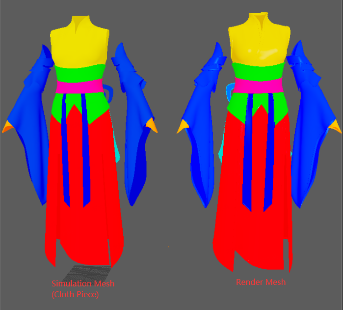
- Method 1: Paint model vertex colors.
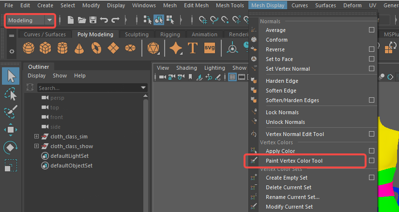
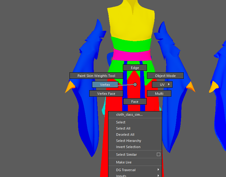
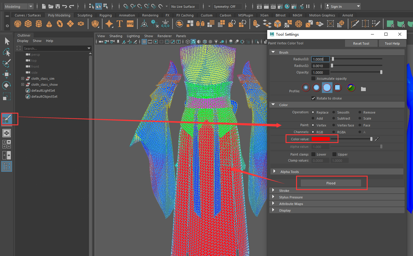
- Method 2: Use color ID maps.
For high-resolution render meshes, add a UV set and arrange UVs in the first quadrant. Set different groups and add different color materials.
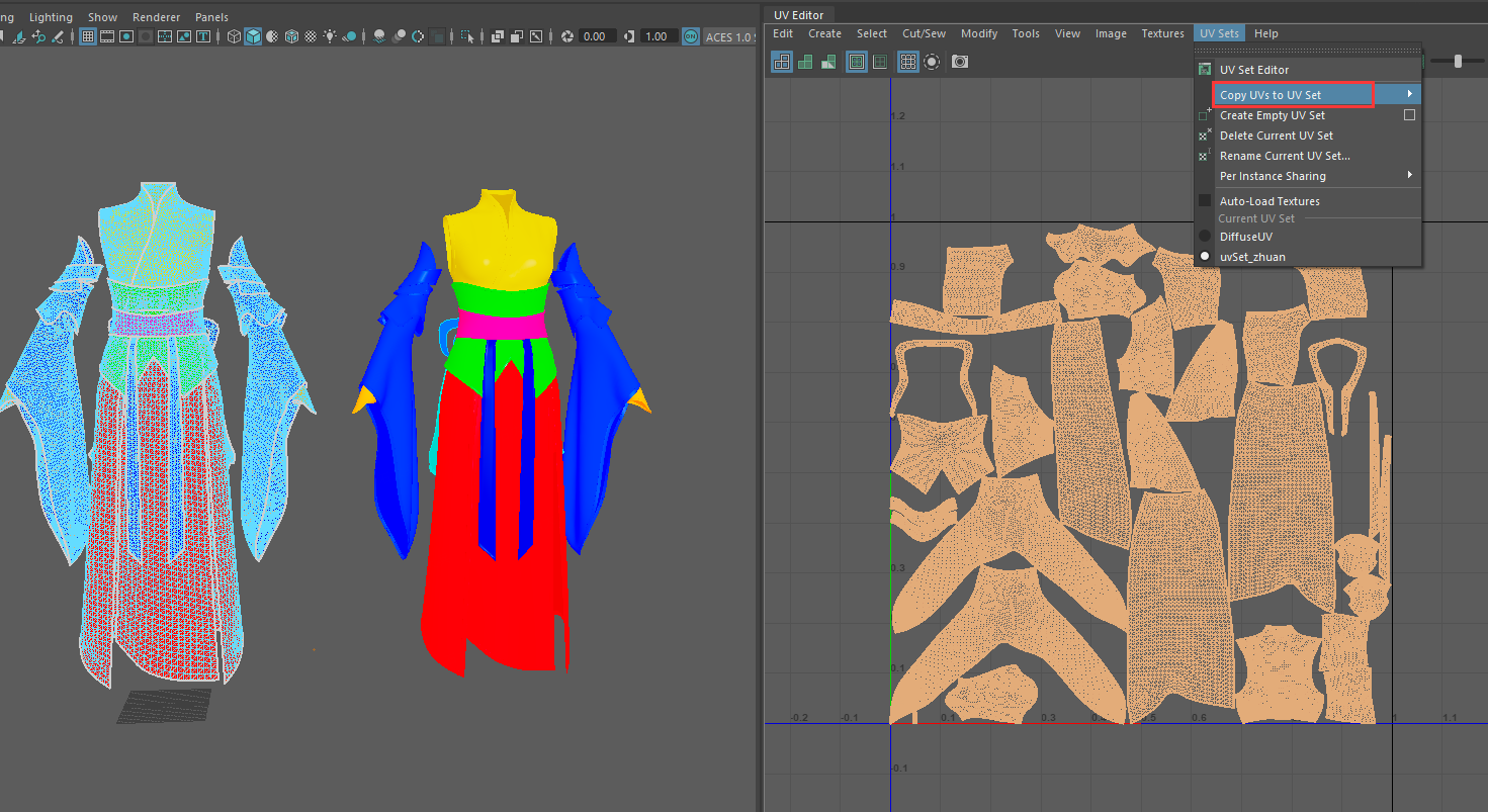
- In face mode, select mesh faces and assign new materials (regular Lambert works).
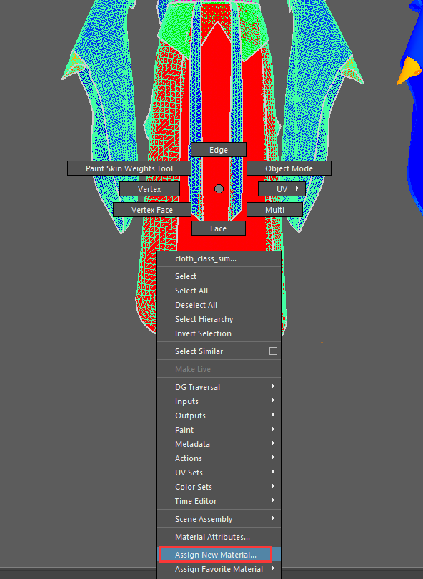
- Assign different colored materials to all meshes.

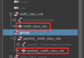
- Copy the mesh.
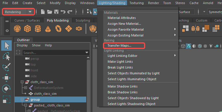
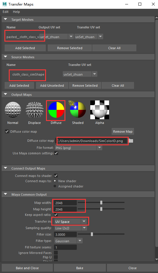
- Select Bake -> Transfer Maps to bake and export UV maps with colors.
- Target Mesh: Copied mesh.
- Source Mesh: Mesh with grouped materials.
- Diffuse Color Map: Storage path and file name.
- Transfer: Select UV space.
- Find the baked ID map in the directory.

- Use the above method to get the ID map for the simulation mesh (no need for a new UV set for the simulation mesh, UV0 channel can be used).
2. Setting Up Proxy in UE
- Create the simulation mesh as a clothing asset using the generic mesh simulation function to create it as a Style3D clothing asset from the FBX.
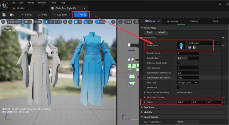
- Proxy Mode:
- Click Proxy Mesh Proxy Mode, add a render mesh skeletal mesh component, and set the Offset.
- Show Mesh Colors: Check Show Color to display vertex colors in the 3D window.
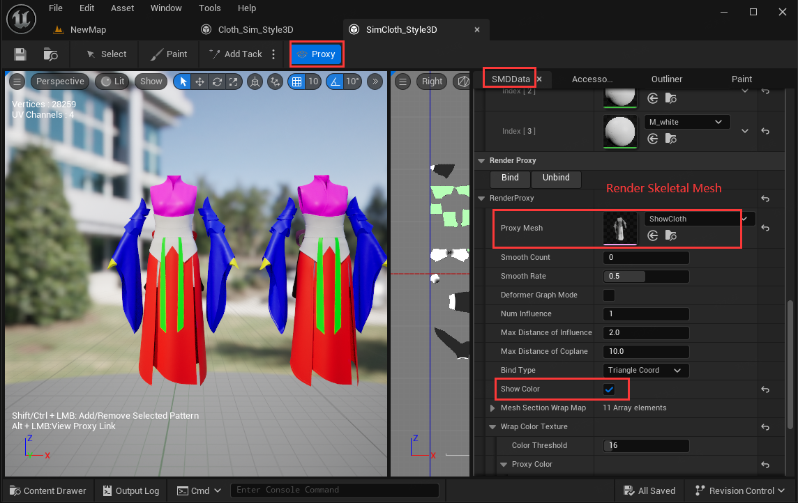
- Load Color Map (Optional):
If no color map is configured, the model's vertex color is displayed. If a color map is configured, the color of the map is displayed.- Wrap Color Texture: Enter the color map in the respective fields.
- Proxy Color: Render mesh color map.
- Piece Color: Simulation mesh color map.
- UV Channel: UV channel to apply the map.

- Creating Proxies:
- Clear all proxies by right-clicking before creating new ones.
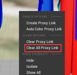
- Method 1: Automatically create proxies for areas with the same color by right-clicking and selecting Auto Color Proxy Link.
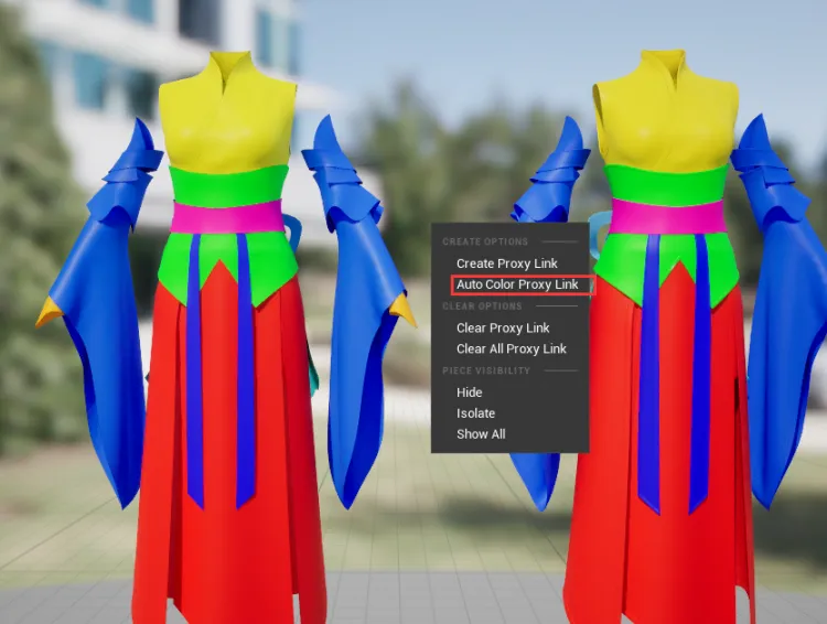
- Method 2: Manually create proxies by selecting the mesh of the simulation and render meshes and right-clicking to Create Proxy Link.
- Mesh Selection Notes:
- Single-clicking the simulation mesh selects the piece, single-clicking the render mesh selects the section.
- Double-clicking either mesh selects the topologically connected same-color area.
- Shift/Ctrl + single-click adds/removes pieces in the simulation mesh or sections in the render mesh.
- Shift/Ctrl + double-click adds/removes color areas.

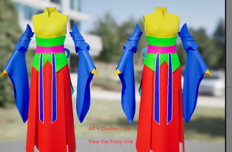
- View Proxy Relationships: Hold Alt and double-click the color area of the render mesh to simultaneously display the simulation mesh with proxy relationships.
- Clear Proxy Relationships:
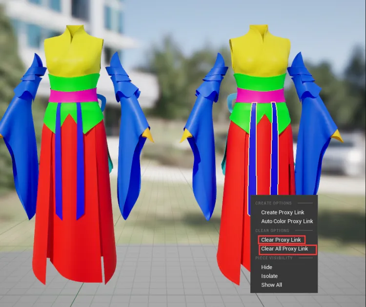
- Select a color area, right-click, and choose Clear Proxy Link to clear the current proxy relationship.
- Right-click and select Clear All Proxy Link to clear all grouped proxy relationships.
- Save and Apply Proxies: Click Bind to apply all created and modified proxy relationships. Reset render mesh offset and hide the simulation mesh.


Common Issues
- When both index proxy relationships and color grouping proxy relationships exist for a piece, the color mode proxy (higher priority) is used. If no color mode proxy exists, the index mode proxy data is used.